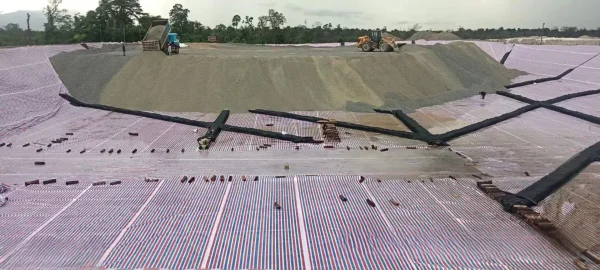
Heap construction involves stacking ores or agglomerated ores onto the bottom liner of the Heap leaching area according to the designed geometric dimensions. The constructed ore heap should feature good and uniform permeability, as well as structural stability. This ensures that during the leaching process, the leaching agent can penetrate uniformly across the entire cross - section of the ore heap at the required liquid - distribution intensity. Meanwhile, it prevents occurrences such as collapse at the edges of the ore heap or local washouts. Therefore, great attention must be paid during operation. In production practice, there is another type of heap leaching method. Ore extracted is transported directly to the heap leaching platform for leaching without prior crushing. In some cases, leaching even takes place at the blasting site. The particle size of the ore usually ranges from 100 to 200 mm or even larger, resulting in a leaching cycle that can last half a year or even longer. Since this type of heap leaching is relatively simple, it is often not studied as a typical form of heap leaching.
Selection of Heap Leaching Sites and Laying of Bottom Liners
The selection of the Heap leaching site is related to infrastructure investment, including site processing, transportation roads, and pipeline layout. The bottom liner of the heap leaching site and its laying are crucial for heap leaching production, especially for large - scale heaps. Therefore, the quality of the bottom liner must be ensured.
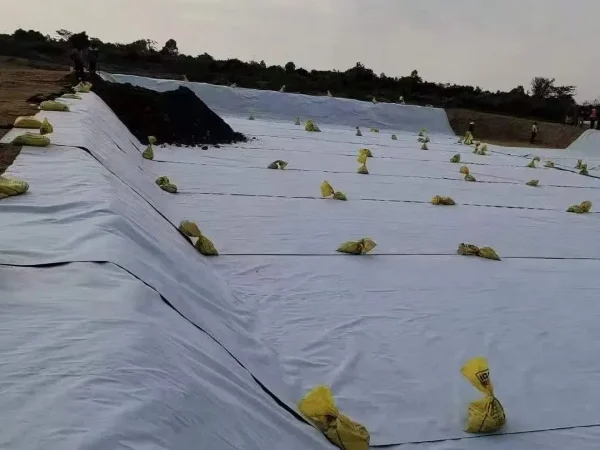
1. Basic Requirements for Heap Leaching Sites
The site should have sufficient bearing strength to withstand the total pressure of the ore weight and transportation equipment.
It should have a certain topographic slope, which is conducive to site trimming and the flow of leachate.
There should be enough area for heap construction and transportation passages. For mines with development potential, future expansion possibilities should also be considered.
2. Selection and Laying of Bottom Liners for Heap Leaching Platforms
2.1 Selection of Bottom Liners for Heap Leaching Platforms
Bottom liners for heap leaching platforms can be classified into two types: permanent and temporary. The former requires a long construction time and high costs, making it suitable for medium - to - large - scale mines with a long service life. In contrast, temporary bottom liners are used only once, require a short construction time, and are low - cost. They are suitable for mines with a service life of less than 5 years. Additionally, the surrounding environment also plays a role. If the area for constructing the heap leaching site is limited, a permanent heap leaching platform can be built. Conversely, if there is a large - area slope nearby and the ore - transportation distance is short, a temporary heap leaching platform can be constructed.
2.2 Several Commonly Used Bottom Liner Materials
Clay and Bentonite: When there is a large amount of clay near the heap leaching site, using a clay bottom liner is a suitable choice. This bottom liner can be compacted in three layers, each about 150 mm thick. The permeability coefficient of this bottom liner is 1.0×10⁻⁷ cm/s, which meets the requirements of environmental protection. Since bentonite (especially sodium - type) has strong water - absorption properties and can expand 10 - 30 times in volume after absorbing water, adding an appropriate amount (about 4%) of bentonite to clay can significantly reduce the permeability of clay. This type of bottom liner is easy to lay and has a low cost. The foundation should be compacted, and the slope should be gentle to prevent erosion of the bottom liner during the heap leaching process.
Asphalt and Concrete: When asphalt or concrete is used as the bottom liner, its anti - seepage and compressive strength are related to its thickness. Usually, the thickness ranges from 150 to 200 mm. When constructed well, the permeability coefficient is between 1.0×10⁻⁹ cm/s and 1.0×10⁻¹⁰ cm/s. However, this type of bottom liner is relatively expensive and prone to cracking.
High - Density Polyethylene Films (Plates) (HDPE): When high - density polyethylene and other synthetic materials are used as the bottom liner, the thickness is only 1 - 2 mm. Its permeability coefficient is less than 1.0×10⁻¹³ cm/s, and it has medium puncture - resistance ability. It is suitable for ores with a particle size of less than 20 mm and can be reused multiple times. High - density polyethylene soft plates can be bonded on - site using cyclohexanone. The construction method is simple, but strict requirements are placed on the quality of the welds. In foreign countries, this material is often selected for the bottom liners of heap leaching sites (including finished - liquid ponds).
2.3 Bottom Liner Structures
Single - Layer Bottom Liners: When clay, asphalt, or concrete is used for single - layer bottom liners, they bear a relatively high stress and can control the stability of the ore heap together with the foundation. When synthetic materials are used, especially when the synthetic materials are laid on a foundation of fine - grained materials, the frictional contact strength is very low, which can ensure the stability of the ore heap.
Double - Layer Bottom Liners: Double - layer bottom liners are composed of two types of bottom - liner materials. The two layers can be in direct contact or have a drainage layer or buffer layer in between. The drainage layer used for leak monitoring can collect and recycle the leachate. The drainage layer can be made of materials such as fine sand, and its addition can also improve the stability of the ore heap. The upper layer of the double - layer bottom liner is often the working cushion layer to ensure the recovery of the leachate, while the lower layer is the backup layer to prevent the leakage of the solution into the environment. Commonly, the working layer of the double - layer bottom liner is made of synthetic materials such as HDPE and PVC, and the backup layer is made of clay.
Triple - Layer Bottom Liners: Triple - layer bottom liners are often composed of one layer of PVC or HDPE soft plate and two layers of clay, or two layers of PVC and one layer of clay. There is a relatively high possibility of ore - heap sliding with triple - layer bottom liners. To prevent sliding, at least one drainage layer should be provided between the bottom - liner layers. Triple - layer bottom liners are less commonly used.
2.4 Laying of Bottom Liners
The laying technology and quality of the bottom liner seriously affect its function. When laying a clay bottom liner, it is necessary to avoid the rainy or dry seasons to prevent the bottom liner from cracking due to water loss. The specific approach is to first lay a layer of clay, bentonite, or fine tailings on the foundation, compact it, then lay plastic films or rubber sheets, add a layer of clay or fine sand, and finally cover a layer of large - sized ore as a protective layer.
When there is a height difference in the foundation, the laying of synthetic - material bottom liners should start from the lowest point and proceed upwards. Avoid creating wrinkles. A seamless roller machine can be used for laying, and welding is preferably carried out on - site. The welds should be uniform, and their arrangement direction should be perpendicular to the possible movement path of the ore heap. In addition, the laying area of the bottom liner of the heap leaching site should be slightly larger than the actual bottom area of the ore heap.
- Random Content
- Hot content
- Hot review content
- Industrial concentrated nitric acid 55%-68%
- Ammonium Nitrate Porous Prills
- Antimonium Tartrate Potassium
- Triethanolamine(TEA)
- Hydrogen Peroxide
- 2-Hydroxyethyl acrylate (HEA)
- Phthalic anhydride
- 1Discounted Sodium Cyanide (CAS: 143-33-9) for Mining - High Quality & Competitive Pricing
- 2Sodium Cyanide 98% CAS 143-33-9 gold dressing agent Essential for Mining and Chemical Industries
- 3China's New Regulations on Sodium Cyanide Exports and Guidance for International Buyers
- 4International Cyanide(Sodium cyanide) Management Code - Gold Mine Acceptance Standards
- 5China factory Sulfuric Acid 98%
- 6Anhydrous Oxalic acid 99.6% Industrial Grade
- 7Soda Ash Dense / Light 99.2% Sodium Carbonate Washing Soda
- 1Sodium Cyanide 98% CAS 143-33-9 gold dressing agent Essential for Mining and Chemical Industries
- 2High Purity · Stable Performance · Higher Recovery — sodium cyanide for modern gold leaching
- 3Sodium Cyanide 98%+ CAS 143-33-9
- 4Sodium Hydroxide,Caustic Soda Flakes,Caustic Soda Pearls 96%-99%
- 5Nutritional Supplements Food Addictive Sarcosine 99% min
- 6Sodium Cyanide Import Regulations & Compliance – Ensuring Safe and Compliant Importation in Peru
- 7United Chemical's Research Team Demonstrates Authority Through Data-Driven Insights





Online message consultation
Add comment: